
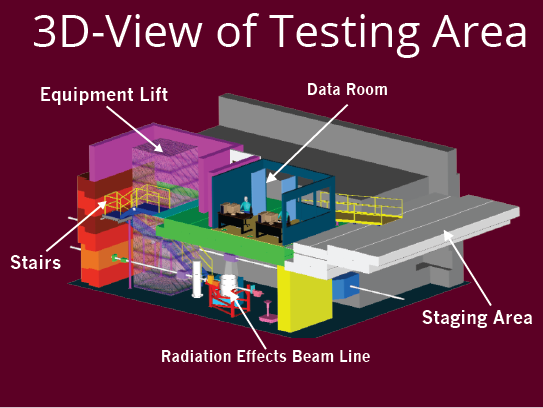
Radiation Effects Facility
Radiation Effects Facility
Various ion beams have been developed specifically for the Radiation Effects Facility. These beams provide for a wide scope of LET with high energies for deep part penetration. Time for beam species changes will vary, but with species that have the same energy per nucleon change times are about one half hour.
Beams can be delivered with a high degree of uniformity over a 1.8" x 1.8" cross sectional area for measurements inside the vacuum chamber and 1" diameter circular cross sectional area for the in-air station. Uniformity is achieved by means of magnetic defocusing.
A degrader foil system makes it possible to set the desired beam LET value at a particular depth inside the target without changing the beam or rotating the target. The beam energy is reduced by means of a degrader system with foils having a suitable thickness and orientation with respect to the incident beam. Each foil can be inserted, withdrawn, and rotated remotely through use of computer controls.
The intensity of any beam is easily regulated over a broad range spanning several orders of magnitude in a matter of seconds. This can be done by the operator on duty at the users request. The target exposure system is fully automated. Exposure can be set for a certain time, total accumulated fluence, or can be manually stopped at any time.
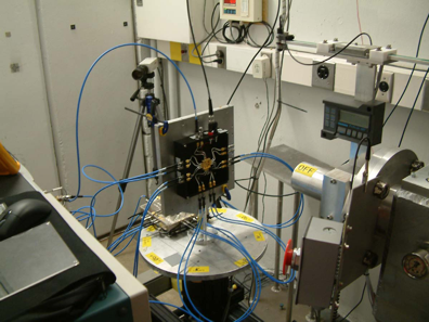
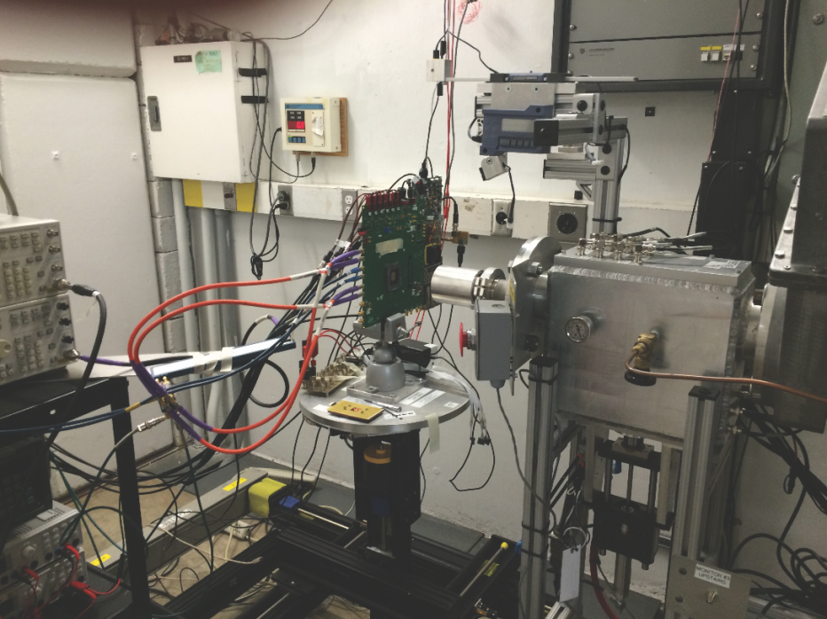
Our in-air station is located at the end of our dedicated heavy ion beam-line. The station consist of a rotating platform and a removable target mounting fixture. most users to our facility prefer the in-air station over the vacuum chamber due to its easy access for set-up and target changes.
TARGET MOUNTING
The mounting fixture for the in-air station has the same dimensions as the vacuum chamber mounting fixture. Specifications for a typical board to be mounted are detailed here . The mounting fixture is removable and is attached to a rotary platter. Detailed drawing of the frame is also available. The platter is 15 1/4" in diameter and can hold a load up to 100 lbs. For mounting directly to the platter please refer to this drawing.
TARGET POSITIONING SYSTEM
The in-air station allows for the motion of the target in four directions: X, Y, Z and Theta. X and Y are the horizontal and the vertical axis in the target plane, respectively. The Z-axis is in the direction of the beam-line, with theta being the clockwise and counter-clockwise rotation about the y-axis.
Range of motion is listed below:
X-Axis: +6.8" / -6.9" about the beam-line center
Y-Axis: 11.6" from the platter to the beam-line center at its lowest position, 1.3" from the platter to beam-line center at its highest position
Z-Axis: Frame is 1" from exit window at its closest position (you may offset your test board from the frame for a shorter air gap from the exit foil)
Theta: 86.8 degrees CCW / -149 degrees cw (looking up the beam line)
Target position verification is provided by the means of a CCD camera aligned with the beam path. a narrow laser beam attached to an electronic scale is used to determine the air gap distance between exit window and target. The standard aramica exit window has a 1"-Diameter opening. A 1.75"-diameter and 1.5"-diameter window are also available as needed. Our software allows you to account for air gaps and exit window thickness for range and LET calculations. The size and shape of the beam aperture may be altered using various collimators.
Hot Air Blower and IR Camera
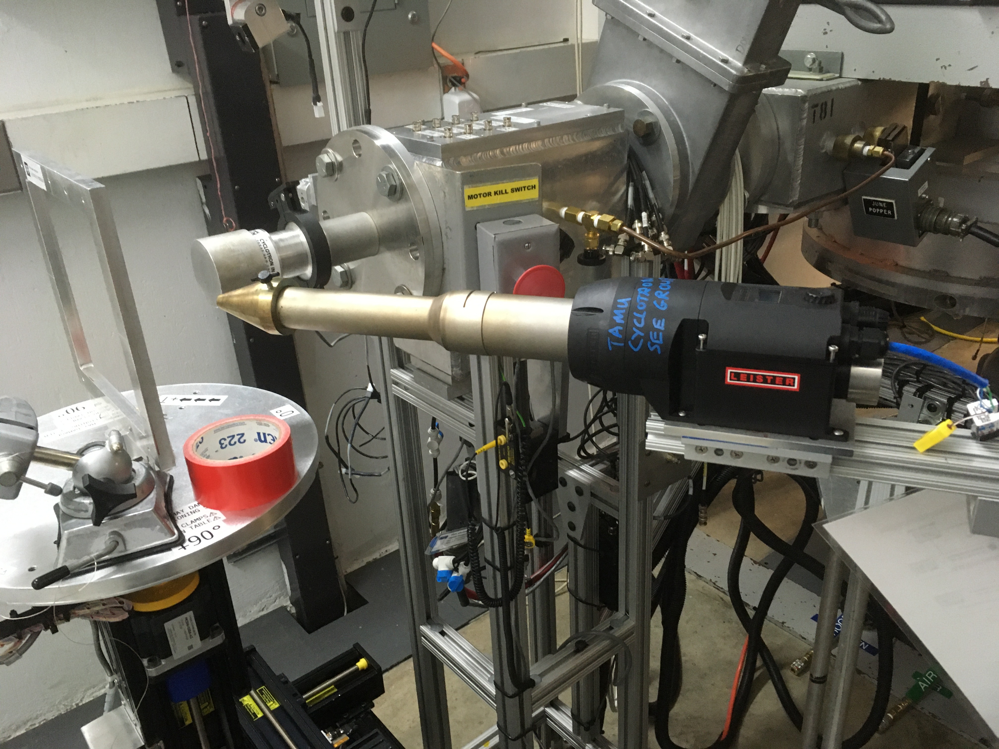
A hot air blower is available for our guest to use to heat devices under test. The blower can be controlled locally at the unit or remotely from the data room.
A FLIR IR camera is also available for use. A software driven control system has been developed for use with both the hot air blower and the IR camera.
You can download the user guides here:
Hot Air Blower User Manual
FLIR IR Camera Software Manual
A video demonstration can be viewed here:
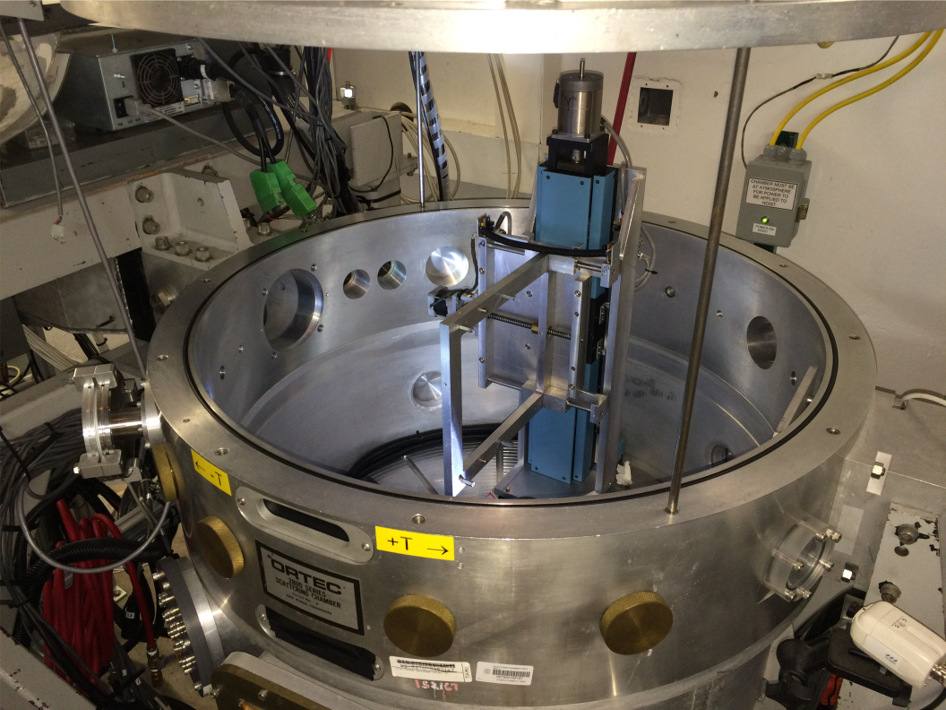
A vaccuum chamber is also available for radiation testing. The chamber has an inside diameter of 30" and a height of 30". Inside the chamber is a target mounting fixture measuring 10" x 10".
Movement of the frame in x, y, z, and directions is
computer controlled. Pumping time to an operating pressure
in the low 10-4 Torr range is approximately ten minutes, while
the chamber vents in two and a half minutes. Target position
verification is provided by means of a CCD camera aligned
with the beam path. The size of the exposed area (up to 1.5"
x 1.5") is controlled by a pair of remotely adjustable horizontal
and vertical slits. Five 50-pin hermetically sealed D-shell
male connectors and 19 BNC connectors are provided
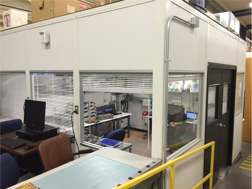
The K500 data room is located directly above the heavy ion beam line. The room is independently cooled and well insulated from building noise. The room includes four video monitors for test observation and two 27" hdmi compatible monitors user laptops. Wired internet connections are available inside the data room and in the setup area just outside. Temporary wireless network accounts are also available.
CABLING
Located on the floor of the data room are two four inch diameter cable passages to provide the shortest distance possible between your equipment and your test board. From a table top in the data room to the top of the in-air station platter is approximately 15 feet.
In addition, a 17 port bnc patch panel between the data room and beam line area is available. Two db9 serial cables and two db25 cables are permanently installed. Various ribbon cables, GPIB cables and additional serial cables are also available if needed.
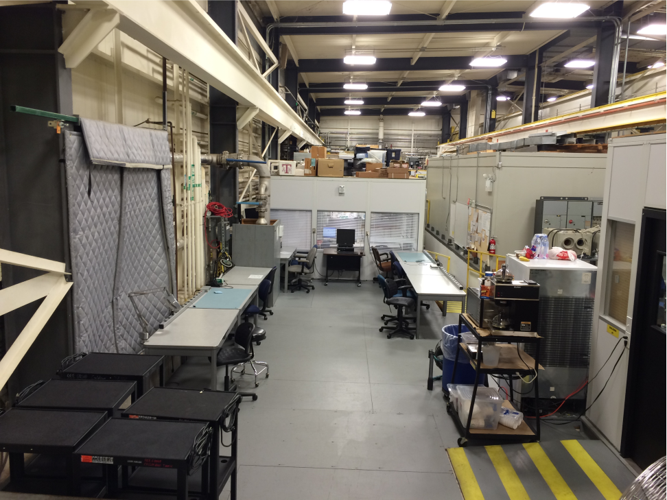
The K500 setup area is located just outside the data room. This area can be used for test prep and equipment storage during your visit. We have various tools and supplies stored in nearby cabinets and tool boxes. A JBC soldering station and stereo microscope are also available. Work tables in the setup area offer access to wired network connections. Wireless access is also available. For your convenience we provide a full-sized refrigerator, microwave oven and coffee maker.